DIY Page - Ortobi82
75% ortholinear keyboard
2025 EDIT
This was my first try in PCB designing and board making, a real use case of making something with KiCad, FreeCAD and many others as a beginner.
Board Design & Developpement
Old Versions (1, 3)
Before using KiCAD, i dabbled with Fritzing because i was watching many tutorial using it. I bought it and understood many things. But then i watched people using something else called Eagle. Long story short i used KiCad. which i tried and tried until i found out i had to use some nighly build because pre-6.0 versions are just the worst to use (the 6.0 wasn't out yet)
First version used Elite C microcontroller a Pro Micro clone. I lost my shit when i had to build a firmware with QMK tools.
The transistion between pre-6.0 and 6.x was painful, a huge majority of tutorials were made in almost prehistoric times,completly irrelevent. I also created a full folder of parts once i got familiar with the nightly build, after that i continued to use this build even after final 6.x release.
I had some pcb routing errors, i scrapped all the QMK stuff and went for something easier and appealing in Micropython/Circuitpython bringing me back to the time i used Fritzing. And I learned I cannot do matrixes over a MUX and direct inputs from the board -despite all the documentation I read. i need to read docs better. The last PCB i did was ok-ish.
I've had help for routing from a engineer not specialized in pcb manufacturing but that knew more about it than me, and he showed me some stuff, and from that fresh knowledge i did some mistakes.
For firmware choices i had a hard time understand how i'm supposed to use QMK and it was at the time the point when i saw the project called KMK the CircuitPython varient of QMK, which its based on C.
Current Version (6)
That one is actually perfect, no routing errors, no more uses of multiplexers, more barebone. An it can goes with a lot of boards such as Arduino's Pro Mini, Sparkfun's Pro Micro. Elite C board. Any controllers with the same form factor and pinouts as Pro Micro can go.
Intended to use this version with AdaFruit's KB2040|RP2040 "KeeBoar" for testing purposes. It supports Micro/Circuitpython, and i saw it can be flashed with Arduino code too.
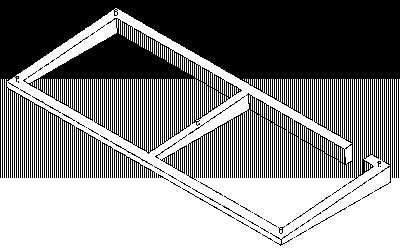
Enclosure Design
Version 1
Early versions used cardboard the same folds as a shoebox.
I used FreeCAD for this kind of work. i didn't designed many enclosure cases design. it was my first time. I don't have a 3D printer so a friend is actually give me some help there. It use additionnal parts, 5 M3 female threaded knurled nuts with 5 round and cruciform (Philips) M3 screws.
The bill of material was nice and easy, but for cheaper build i also designed nails and holes in the board that can fit really well.
Version 2
That one was really barebone exposing the most of the board, and set the board in place with small pegs. It wasn't a good design choice but i did not know any better, i had to try.
Version 3
That one is the a mix of the first one, where the bases are halfcut really flush with the board making the joint, i used staples and it worked amazingly, and for the top i used laser cutted top. i tried wood and transparent pvc.
Version 4
Didn't had the resources to try that one but i tried to remake a better 'construction bloc'-like version such as the 2. and seems okey but never tried it
Assembly
End point 1
Prototype is finished
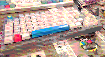
3D printed in 4 parts with a newly built Prusa MK3S+ Printer. All parts needed revisions after the print.
This was the most enlighting build i ever did. the first one but i also manage to get it together over time. I still find some little modification to do, other layers to test and it's a great build for doing so.
End point 2
After few time, after making tests with the laser cut tops, i completly removed that and i just make my board visible, stapple the two bottom and call it a day.Return to DIY index page